|
This page contains the list of Brother drivers available for free download. This list is updated weekly, so you can always download a new driver or update driver to the latest version here. We offer Brother drivers for Windows 8 32 bit / 64 bit, Windows 7 32 bit / 64 bit, Windows XP, Mac OS and Linux. It is very easy to download Brother driver. Brother MFC-240C USB printer supports borderless image printing while at the same time prints a maximum resolution of 6,000 by 1200 dpi at a speed of 25 pages per minute. Free Download Driver For Brother Mfc-3220c PrinterBrother drivers Is your Brother printer getting low on ink? Pick the right ink cartridge or laser toner for your printer here. You can choose a compatible cartridge model from our. This page contains the list of Brother drivers available for free download. This list is updated weekly, so you can always download a new driver or update driver to. This page contains the list of Brother Printer drivers available for free download. This list is updated weekly, so you can always download a new driver or update. The functionality of the Brother HL-5270DN series is based on the capability of its printing processor which runs at 266 MHz and supported by a standard 32 MB memory.
0 Комментарии
Download Compaq Sound driver for Windows 7, 8, XP Download Driver C-media 8738 Driver VistaToshiba laptop drivers, dell laptop drivers, acer laptop drivers, hp laptop drivers, sony laptop drivers, laptop drivers for windows 7, asus laptop drivers. Free Driver Download. World's most popular driver download site. Vgn-fz490 Driver DownloadDownload Compaq Sound drivers for Windows 7, Windows 8, Windows XP. On this page you can download Compaq ESS 688/1688 drivers. Download driver for all device in thailand.Search drivers for your device type and easy download driver. Download Compaq Sound drivers for Windows 7, Windows 8, Windows XP. On this page you can download Compaq ESS 688/1688 drivers. This FAQ complements Sun's official Java Web Start FAQ page and aims to provide you with information that is not included on the official page for whatever reason.  
Here is a Simple demonstration of Debugging Jdbc N/W Connectivity issues. Some very basic and common tools and simple Jdbc programs helps us a lot in debugging the. This package is for Mondrian developers and power users. If you are interested solely in Mondrian's analysis capabilities from a user standpoint, download the Pentaho. I am working with the BIRT Report Design Feature that is built into eclipse. I am using this to develop a report for an application we use at work. In BIRT, I added a. I am working with the BIRT Report Design Feature that is built into eclipse. I am using this to develop a report for an application we use at work. In BIRT, I added a data source which would be the database that I want to pull my data from. The problem occurs whenever I try to access Data Sets to write my query that will specify the data that I want to pull in. When I try to do this I get an error: Does anyone know if I need to get certain .jar file and where to put it? Or do I need to download a special driver or plugin or what exactly do I need to do to resolve this? I am fairly new to BIRT so please bare with me. If anyone has any suggestions it will be greatly appreciated. Thank you , Dave cannot load JDBC Driver class: net.sourceforge.jtds.jdbc.Driver is basically because your application has dependency on jtds.jar which is unavailable in the classpath so first download the jar from here and add it to the classpath. This is where you may want to get start with','url':'http://stackoverflow.com/questions/25311635/eclipse-cannot-load-jdbc-driver-class-net-sourceforge-jtds-jdbc-driver','og_descr':'I am working with the BIRT Report Design Feature that is built into eclipse. I am using this to develop a report for an application we use at work. In BIRT, I added a data source which would be the 
Version Date Description; in scm: next: Lost dbunit.org, 2.5.1: April 11, 2015: allowEmptyFields property, column aliases POI 3.11, 2.5.0: Apr 24, 2014: CSV dataset. 7,665 FedEx Jobs available on Indeed.com. one search. all jobs. Fed Ex Swing Driver GolfGet the latest news and analysis in the stock market today, including national and world stock market news, business news, financial news and more. 7,699 FedEx Jobs available on Indeed.com. one search. all jobs. FedEx Jobs, Employment | Indeed.com A Website About FedEx Ground Lawsuit. to network with forums, surveys, chat, news, personal journals and more. Albuquerque News and Weather, Santa Fe, Rio Rancho, New Mexico | krqe.com. Motorola RSD Lite v.6.1.5 - flasher for Motorola phones and smartphones. Motorola RSD Lite. Motorola V3re Driver Download Windows 7Flash&Backup With 'Flash&Backup' tool you will be able to safely update the firmware and restore an operable configuration even if your Motorola phone doesn't start. With "Flash&Backup" tool you will be able to safely update the firmware and restore an operable configuration even if your Motorola phone doesn't start up anymore. Tons of Motorola fans and modders all around the world already use this tool to backup settings before uploading new firmware or switching "dangerous" options. Supported phones* Motorola C380 Motorola C381P Motorola C390 Motorola C650 Motorola E1 ROKR Motorola E1000 Motorola E1070 Motorola E375 Motorola E398 Motorola E770v Motorola K1 KRZR Motorola K3 Motorola L2 Motorola L6 Motorola L7 SLVR Motorola L7e Motorola U6 PEBL Motorola V180 Motorola V186 Motorola V188 Motorola V220 Motorola V235 Motorola V3 Motorola V300 Motorola V360 Motorola V3i Motorola V3r Motorola V3re Motorola V3t Motorola V3x Motorola V3xx Motorola V400 Motorola V500 Motorola V547 Motorola V6 MAXX Motorola V600 Motorola V620 Motorola V635 Motorola V980 Motorola V9 RAZR2 Motorola Z3 RIZR Operating with other models is possible but not guaranteed. *)In the case of new changes in the official firmwares, some phones in this list may be not supported anymore. Please contact us in such a case. This site is not owned and/or affiliated by the Motorola company. www.Motorola-Tools.com Chan_mobile (used to be chan_cellphone) — Use Bluetooth cell / mobile phones as FXO devicesAsterisk Channel Driver to allow Bluetooth Cell/Mobile Phones to be used. SmartMoto Mobile Service Software Unlock Manual. Download PDF English or Italian version of User's Manual for SmartMoto v.1.23 and lower. SmartMoto is a flashing.
I had the older R7 XD line in my bag for one season and ended up getting rid of them due to many of the same issues you mention. The irons were dialed in for high and. Find great deals on eBay for 5 wood golf club 3 wood golf club. Shop with confidence. Is the last r7 the best of the lot? Share this with your golf buddies:Email Hp Deskjet 895cxi Xp Driver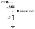
Acoustic Circuits including ultrasonic designs. DiscoverCircuits has 40,000+ free electronic circuits. Power ultrasonic driver (14/05/11) Important note (11/10/12) The circuit described here (i.e., a voltage-fed inverter connected directly to an ultrasonic. ABQ Techzonics,Albuquerque,NM,sound,audio,ultrasonic,infrasonic,test equipment,analyzers,meters. But for these DIY ultrasonic range finders, the choice of the transducers are really not that critical and this transducer really hits the performance to. The circuit described here (i.e., a voltage-fed inverter connected directly to an ultrasonic transducer) will probably be happy driving low-powered transducers, below about 100W. However, as I've read more about ultrasonic transducers and driving circuits, I've realised that there are problems using this circuit for higher powers. The proper electrical model for an ultrasonic transducer is a capacitance in parallel with an LCR series resonant circuit. The fixed capacitance corresponds simply to the electrical capacitance of the transducer, neglecting mechanical oscillation effects. The LCR circuit corresponds to the resonant behaviour of the transducer. Therefore, if the transducer is connected directly to the output of a voltage-fed inverter, the bridge transistors will charge and discharge the fixed capacitance, resulting in large current spikes at the switching transitions. For small transducers, this isn't really a problem because the transistors can handle the spikes, but it becomes a problem for larger transducers. To get around this problem, you need to use a matching network to adapt the electrical properties of the transducer to something that the inverter is happy driving. Matching networks come in many different forms, but the most common are LC and LLCC. Do a Google search on them and you should find some useful results. Suppliers (23/01/13) Some interesting suppliers of ultrasonic transducers and related equipment: Introduction On this page, I describe the construction of a power supply for a 70W ultrasonic tank transducer, and the machining & tuning of an aluminium horn. I originally started all this in order to do ultrasonic drilling, but could find no simple, cheap means of driving high-power transducers. "Proper" ultrasonic horns are usually made from titanium, and the power sources are usually fancy affairs with auto frequency tuning. However, I found that, for the power levels I'm interested in, an aluminium horn works perfectly well, and it is possible to drive the transducer with a manually-controlled oscillator and inverter. I won't go into too much detail on the principles behind piezoelectricity and these kind of ultrasonic transducers - I assume you know a bit of background since you're reading this. I'm using a 28kHz, 70W bolt-clamped Langevin transducer (part number SMBLTD45F28H) which was bough from Steiner & Martin (http://www.steminc.com/) a few years ago for around $30-$40. For photos of it please scroll down or see their website. These are typically intended for ultrasonic cleaning, sonochemistry, low-power welding etc. On the surplus market, they can sometimes be found inside cleaning tanks. Driving requirements - measuring impedance spectra An ultrasonic transducer is a lump of metal and ceramic which has a particular resonant frequency. To operate the transducer at resonance, it must be driven with a high-frequency AC signal. Voltages for power ultrasonics are typically high, in the hundreds of volts. The best way of determining the resonant frequency is to plot an impedance spectrum of the transducer. This is usually done with very expensive network analysers, but it can also be done with a simple USB oscilloscope and sweep frequency generator, if the oscilloscope software has suitable capabilities. The circuit used is shown below. "Drive" comes from the output of a sweep frequency generator. "Current sense" goes to the USB oscilloscope. In the example I'm giving here, the sweep parameters are a linear sweep from 20kHz to 60kHz in a time of 100ms. The generator has a trigger output at the start of the sweep which is used to trigger the USB oscilloscope. If we assume that the drive voltage stays constant (i.e. the transducer doesn't load the output of the generator significantly), then we can determine the impedance of the transducer from the magnitude of the current signal. I'm using PicoScope software (http://www.picotech.com/picoscope-oscilloscope-software.html), version 5. This has the ability to overlay successive traces to form an "envelope" of the waves. If we do this with the current sense waveform, we get the first picture shown below (this has been contrast-enhanced). Although the scope can't pick up individual cycles because of the very slow scan speed (100ms), it can record the amplitude of the waves, shown by the envelope of the black area. We can then use WinDig (http://www.unige.ch/sciences/chifi/cpb/windig.html) to digitise the envelope. When using WinDig, instead of entering the oscilloscope time for the horizontal axis (100ms to 200ms), we enter the frequency range that the scan covers (20kHz to 60kHz). This results in a "spectrum" showing the amplitude of the current at different frequencies. Finally, it's a simple matter to work out the impedance of the transdcuer from this, shown in the second photo below. Note the logarithmic vertical scale. There are three plots shown. Take the one of the bare transducer. At about 28.5kHz, the impedance drops to a minimum. This is the mechanical resonant frequency, and is where we want to drive the transducer. This resonance appears like a series LC electrical resonance to the driving circuit. Current and voltage are in phase. Just above, at about 31kHz, there is an anti-resonance. This has a maximum impedance, and appears like a parallel LC electrical resonance. At higher frequencies, 50kHz, another resonance appears, again followed (52kHz) by an anti-resonance. These higher resonances correspond to other, weirder vibration modes of the transducer and we're not interested in them. Now notice the effect of adding a mismatched horn, both with and without a tip (still referring to the second picture above). This was a piece of aluminium I'd machined before to totally the wrong dimensions - I only show it out of interest. The fundamental resonance with the horn present is lower than that of the bare transducer. Also, the impedance at resonance is higher, meaning that less power can be supplied to the transducer. Note also that, the further away from the bare transducer resonance, the higher the impedance with the mismatched horn and tip. Conclusion: for optimum power transfer, the resonant frequency of the horn must be matched to that of the bare transducer. This can be guessed roughly, as the horn should be ½ a wavelength long, but generally horns are made longer and machined down whilst measuring the resonant frequency, in order to tune them exactly. This is what I attempted to do here, with some success. Making and tuning the horn I decided to cast an aluminium horn. I wasn't entirely sure if a casting would work satisfactorily, but I didn't have a piece of aluminium bar big enough at hand. So, I made up a quick pattern from some lengths of pipe, and then cast it in aluminium in a sand mould, using the electric melting furnace . The horn is a step horn, which amplifies the displacement of the ultrasonic transducer. The large end (44mm dia.) is connected to the transducer, the small end (19mm dia.) to the tool or tip. The horn should be half a wavelength long, but it's best to make it a bit longer and machine it down to achieve exact frequency tuning. A vibration node exists at the step in the horn (in the middle), which enables the horn to be mounted here. I turned a small flange at this point, which can then be clamped between two O-rings. It cannot be clamped absolutely rigidly, because although this is a longitudinal node, it is a radial antinode, and the O-rings must accomodate radial vibration of the horn. I cast an aluminium ring clamp which provides a convenient means of mounting the horn on a laboratory stand. The horn is threaded at both ends, for attachment to the transducer and to the tool. At this stage, I was satisfied I now had a transducer+horn system which would resonate at the correct frequency. My next step was to built a driver circuit. Driver I mentioned above that, at resonance, the ultrasonic transducer appears electrically like a series LC resonant circuit. This means that it can easily be driven by a voltage-fed squarewave inverter. I used a little half-bridge inverter driven from an adjustable 0-170V DC supply, which was obtained from a modified site transformer plus variac. Oscillation frequency is manually adjusted with a 10-turn potentiometer in the range 27-29kHz. Resonance is typically around 28kHz. Here is a PDF of the entire driver circuit. Files are also available of the PCB layout of both the inverter board, and the oscillator board. Note (09/05/14): it was brought to my attention that the circuit in the ZIP file is actually different from that shown below. The SD pin of the IR2110 was pulled permanently to 0V, whereas I had modified my original board to include a switch to enable/disable the output. The circuit board files are now correct, and have a separate pin for SD so a switch can be connected. The oscillator and inverter are pretty standard so I won't go into them in too much detail. The oscillator is a 4046 VCO (IC2). IC3 provides adjustable dead-time delay for the inverter. IC4 is the gate driver, an IR2110 chip. These are great little chips, since they can drive both high-side and low-side MOSFETs. The inverter uses two 13A MOSFETs, way overkill, but they were handy. Maximum currents are only around 0.5A. A meter provides an indication of either link voltage or current, selectable with a switch. I built the whole driver inside a PC power supply case, making use of the existing cooling fan. I used two separate PCBs for the inverter and the oscillator, so I could test them individually. I have to stress that the input power supply to this driver must be floating, to allow for safe handling of the ultrasonic transducer. I achieve this by using a site transformer as an isolation transformer. Testing in water with a ½" extension rod Prototype of the driving circuit Transducer and horn mounted on bracket Final, boxed supply Controls - meter, scale select, and tuning adjustment. Note non-linear meter scale! Power connections Innards of supply Oscillator & gate driver PCB Inverter PCB Rear of controls Power connections Completed driver running In operation Here's a quick video showing the tuning process. Resonance is very sharp, maybe only a few 100Hz wide, but the multiturn pot provides fine enough adjustment. Next, here's a video showing cavitation in water. This is using a ½" aluminium bar as an extension, attached to the main horn. Input power is about 50W. The cavitation is powerful enough that it wears away the end of the tip after only a few mintues ! Here's the effect on fresh lemonade, showing the degassing effect of ultrasound. Lastly, check out the page on ultrasonic drilling, which is what originally started me off on all this. Deskjet 895cxi Xp DriverStryker 
Involvement. Mordecai's intro screen in Borderlands 2. Mordecai, along with Roland, Brick, and Lilith, was a founding member of the Crimson Raiders. 
Wiki Line Driver AmplifierThe IAV Stryker is a family of eight-wheeled, armored fighting vehicles derived from the Canadian LAV III and based on the Swiss Piranha III 8×8. Stryker vehicles are produced by General Dynamics Land Systems for the United States Army. It has 4-wheel drive (8×4) and can be switched to all-wheel drive (8×8). The vehicle is named for two American servicemen who posthumously received the Medal of Honor: Private First Class Stuart S. Stryker, who died in World War II, and Specialist Four Robert F. Stryker, who died in the Vietnam War. In October 1999, General Eric Shinseki, then U.S. Army Chief of Staff, outlined a transformation plan for the army that would allow it to adapt to post-Cold War conditions. The plan, named "Objective Force", would have the army adopt a flexible doctrine that would allow it to deploy quickly, and equipped for a variety of operations. An early phase of the plan called for the introduction of an 'Interim Armored Vehicle' which was intended to fill the capability gap between heavy and lethal, but not easily deployable vehicles (such as the M2 Bradley), and easily deployed, but lightly armed and protected vehicles (such as the Humvee). A variant of the Canadian LAV III offered by the General Dynamics-General Motors Defence Canada team was ultimately awarded the contract in November 2000 to produce 2,131 Stryker vehicles of all variants for equipping six rapid deployment Brigade Combat Teams.[On 27 February 2002, the Army formally renamed the Interim Armored Vehicle as the Stryker. It was called the "Interim" Armored Vehicle because it was initially supposed to be a temporary measure until light air-mobile vehicles from the Future Combat Systems program came online, none of which did before FCS was canceled. The Stryker 105mm M1128 Mobile Gun System (MGS) moved into low-rate initial production in 2005 for evaluation, and entered full production in 2007. General Dynamics Land Systems-Canada assembles the Stryker for the U.S. Army in a plant in London, Ontario. The vehicle is employed in Stryker Brigade Combat Teams, light and mobile units based on the Brigade Combat Team Doctrine that relies on vehicles connected by military C4I (Command, Control, Communications, Computers, and Intelligence) networks. The Stryker has come under intense scrutiny from military experts since its introduction in the US Army; this has also been the subject of mass media coverage. General Dynamics's Robotic Systems division was developing autonomous navigation for the Stryker and several other vehicles with a $237 million contract until the program was cut in July 2011. Tank Automotive Research, Development and Engineering Center (TARDEC) has also tested an active magneto rheological suspension, developed by MillenWorks for the Stryker, at the Yuma Proving Ground, which resulted in greater vehicle stability. Over 1,000 Stryker vehicles have been rebuilt by Anniston Army Depot and returned to operations. The US Army plans to improve its fleet of Stryker vehicles with the introduction of improved semi-active suspension, modifications reshaping the hull into a shallow V-shaped structure, to protect against improvised explosive devices (IEDs). Also included are additional armor for the sides, redesigned hatches to minimize gaps in the armor, blast absorbing mine resistant seating, non-flammable tires, an upgrade to the remote weapon station that allows it to fire on the go, increased 500 amp power generation, a new solid state power distribution system and data bus, and the automotive and power plant systems improvements to support a 25 percent Gross Vehicle Weight increase. The upgraded V-hull will be part of the new StrykShield situational awareness kit, which will address many of these upgrades. Allegheny Technologies' ATI 500-MIL armor steel was designated the primary armored plating for the StrykShield package in 2008. The upgrade incorporating lessons learned from combat in Afghanistan is designated LAV-H and General Dynamics had a technology demonstrator displayed at the 2007 Association of the United States Army (AUSA) Exposition. In March 2010, it was reported that General Dynamics and Army were working to incorporate a double V-hull into the Stryker design. In July 2010 the Army awarded a $30 million contract to GDLS to start production of the new hull. On 9 March 2011, the Department of Defense's director of operational test and evaluations testified that the new V-hull design was "not suitable" for long missions in Afghanistan's terrain. The issues are due to the tight driver's compartment and difficulty releasing the seat to extract an incapacitated driver. General Dynamics stated these issues would be corrected before the new Stryker version deploys. The upgrade also adds significant weight to the vehicle, which can cause it to sink into soft ground. In July 2011, 450 Double V-Hull (DVH) variants of the Stryker vehicle were ordered; the total was increased to 742 a few months later and then to 760 in 2012. DVH Strykers include a new hull configuration, increased armor, upgraded suspension and braking systems, wider tires, blast-attenuating seats, and a height management system. By August 2012, the Army's Stryker fleet included over 4,187 vehicles, with 10 flat-bottom variants and 7 in double V-hull designs. In Afghanistan, it retained a 96 percent readiness rate. To upgrade the existing fleet, the Army has implemented an Engineering Change Proposal (ECP) program with the goals of providing a stronger engine, improved suspension, more on-board electrical power, and next-generation networking and computing technology. Phase 1 of the ECP includes an electrical power upgrade to replace the current 570 amp alternator with a higher current 910 amp alternator. The existing 350 horsepower engine will be replaced with a 450 horsepower engine of a commercial off-the-shelf (COTS) design. It will also have a stronger suspension system to improve mobility at higher weights and an in-vehicle network to improve data and video sharing between crew stations in the vehicle. The in-vehicle network will allow more secure and reliable data sharing between systems on the vehicle. This will reduce size, weight, and power consumption of future components. A demonstrator vehicle was to be constructed by summer 2013. On 28 May 2013, Kongsberg Integrated Tactical Systems was awarded a contract from General Dynamics to supply the commander's and driver's smart displays for the Stryker ECP program. The Driver's Situational Awareness Display (DSAD) and the Commander's Situational Awareness Display (CSAD) feature an on-board processor and additional I/O ports for both data and video. As of January 2014, the U.S. Army had two Stryker Brigades that completed the DVH upgrade with a third brigade, the 2nd Brigade, 2nd Infantry Division at Joint Base Lewis-McChord, to be fully upgraded by the end of FY 2016. The Army seeks to have all nine Stryker Brigades equipped with DVH vehicles, but upgrade of the remaining six brigades was unfunded in FY 2016–2020 budget projections. The 2016 timeframe also coincided with the end of U.S. Army Stryker orders, after which the manufacturing facilities for the vehicles would be put in a layaway mode and only revived for Foreign Military Sales or domestic orders to replace battle damage losses. Then in mid-October 2014, the Army approved the procurement of DVH Strykers for a fourth Stryker brigade, with conversions to 360 vehicles to begin in FY 2017. The Strykers will also be the first to receive ECPs to handle the upgrades better than the previous three brigade vehicles, which increased weight, decreased mobility, and added a power burden; previous DVH-upgraded Strykers will get ECP enhancements when funding is available. ECP enhancements include a more robust 450 HP engine, a more powerful 910 amp power generator, a chassis upgrade to handle the new engine, and improvements to the vehicle's internal network. Potential further enhancements may focus on the vehicle's networkability and lethality, which may include an FGM-148 Javelin anti-tank missile attached to the remote weapon station. Upgrading the fourth brigade will keep the production line active through 2018, whereas deciding to upgrade after the line had closed would be more difficult and costly from reopening it. The Army plans to increase the lethality of Stryker ICVs by having half equipped with a 30 mm cannon and the other half given a Javelin missile on the existing RWS in each brigade. The Stryker is based on the LAV III light-armored vehicle, which in turn was based on the Swiss MOWAG Piranha III 8x8. The vehicle comes in several variants with a common engine, transmission, hydraulics, wheels, tires, differentials and transfer case. The M1130 Command Vehicle and M1133 Medical Evacuation Vehicle have an air conditioning unit mounted on the back. The medical vehicle also has a higher-capacity generator. A recent upgrade program provided a field retrofit kit to add air conditioning units to all variants, and production started in 2005 on the Mobile Gun System mounting an overhead GDLS 105 mm automatic gun. For its powerpack the Stryker uses a Caterpillar diesel engine common in U.S. Army medium-lift trucks, eliminating additional training for maintenance crews and allowing the use of common parts. Because of obsolescence concerns, the Caterpillar 3126 engine was recently replaced by a Caterpillar C7 engine and the Allison 3200SP transmission. Pneumatic or hydraulic systems drive almost all of the vehicle's mechanical features; for example, a pneumatic system switches between 8x4 and 8x8 drive. Designers strove to ease the maintainer's job, equipping most cables, hoses, and mechanical systems with quick-disconnecting mechanisms. The engine and transmission can be removed and reinstalled in approximately two hours, allowing repairs to the turbocharger and many other components to be done outside the vehicle.[ Extensive computer support helps soldiers fight the enemy while reducing friendly fire incidents. Each vehicle can track friendly vehicles in the field as well as detected enemies. The driver and the vehicle commander (who also serves as the gunner) have periscopes that allow them to see outside the vehicle without exposing themselves to outside dangers. The vehicle commander also has access to a day-night thermal imaging camera which allows the vehicle commander to see what the driver sees. The vehicle commander has almost a 360-degree field of vision; the driver, a little more than 90 degrees. Soldiers can practice training with the vehicles from computer training modules inside the vehicle. General Dynamics Land Systems is developing a new Power and Data Management Architecture to handle computer upgrades. The Stryker's thermal sights can see out to 7,800 ft (2,400 m; 1.48 mi), compared to 330 ft (100 m) for night vision sights used by dismounted soldiers. This capability allows the vehicle to identify threats far past what dismounts can see report this information to them before they encounter them. The Stryker's hull is constructed from high-hardness steel which offers a basic level of protection against 14.5 mm rounds on the frontal arc, and all-around protection against 7.62 mm ball ammunition. In addition to this, Strykers are also equipped with bolt-on ceramic armor which offers all-around protection against 14.5 mm, armor-piercing ammunition, and artillery fragments from 152 mm rounds. Problems were encountered with the initial batch of ceramic armor when it was found that a number of panels failed in tests against 14.5 mm ammunition. Army officials determined that this was due to changes in the composition and size of the panels introduced by their manufacturer, IBD Deisenroth. A stopgap solution of adding another 3 mm of steel armor was introduced until a permanent solution could be found. The issue was eventually resolved later in 2003 when DEW Engineering was selected as the new, exclusive supplier for the ceramic armor. In addition to the integral ceramic armor, optional packages have been developed. These include slat armor and Stryker reactive armor tiles (SRAT) for protection against rocket propelled grenades and other projectiles, the hull protection kit (HPK), armored skirts for additional protection against improvised explosive devices, and a ballistic shield to protect the commander's hatch. The Army began sending reactive armor tiles to Strykers in Iraq in 2004, as well as tiles for Abrams tanks and Bradley Fighting Vehicles. Tiles have to be specifically crafted for each vehicle type they are fitted to. Insurgents attempted to counter reactive armor by having teams fire multiple RPGs at once, but at close range these groups could be engaged and broken up. Reactive armor can be defeated by tandem-charge weapons like the RPG-29 or by explosively formed penetrators, although the Bradley's tiles can withstand EFPs. In May 2009, General Dynamics and Rafael won a contract to provide SRAT tiles to replace slat armor on Strykers. The additional weight of the two systems is comparable, but reactive armor tiles offer greater vehicle stability and maneuverability and "assured" rather than "statistical" protection. The Stryker also incorporates an automatic fire-extinguishing system with sensors in the engine and troop compartments that activate one or more halon fire bottles, which can also be activated by the driver, externally mounted fuel tanks, and a CBRN (Chemical, Biological, Radiological, Nuclear) Warfare system which will keep the crew compartment airtight and positively pressurized. Reports from military personnel and analysts state that the Stryker is superior to other light military vehicles regarding survivability against IEDs (improvised explosive devices). With the exception of some specialized variants, the primary armament of the Stryker is a Protector M151 Remote Weapon Station with .50-cal M2 machine gun, 7.62 mm M240 machine gun, or Mk-19 automatic grenade launcher. The choice of armament was driven by many factors. The US Army wanted a vehicle that could rapidly transport and protect infantry to and around battlefields. While the Stryker MGS gives light brigades heavy firepower, the baseline infantry carrier vehicle has a light armament. Stryker program officials are working to mount a 30 mm cannon to the ICV's remote weapons station. With the number of MGS vehicles per brigade being reduced, individual ICVs are to be up-gunned. The cannon would give greater firepower without needing to add a turret. The plan is to purchase and test a company set of 30 mm cannons and also determine if they should be issued for every Stryker or have one per company. The Army planned to test stabilized 30 mm cannons in early 2014, including Kongsberg Protech Systems' Medium Caliber Remote Weapons Station. Kongsberg (which makes the M151 RWS on the Stryker) joined with General Dynamics (which makes the Stryker) for the MCRWS in 2008. The MCRWS is not a true turret, which would extend into the crew compartment and take up space. It can be loaded from inside the vehicle, but does eliminate one of the four roof hatches. Test firings of a 30 mm cannon in the Kongsberg MCRWS occurred on a Stryker demonstrator vehicle on 19 February 2014. The cannon showed increased lethality and accuracy over the standard .50-caliber machine gun at ranges from 600-1,550 meters, with four rounds from five-round bursts hitting the targets. Up-gunning Stryker vehicles is expected to give infantrymen greater fire superiority to end firefights quicker. The 30 mm cannon is capable of hitting targets at a range of over 2,000 meters (1.2 mi). Army leaders were impressed with the demonstration and are looking to advance the proposal and add the system onto vehicles in service. After comparative testing of the Kongsberg MCRWS mounted to Stryker vehicles, the U.S. Army approved on 22 April 2015 the equipping of 81 of the 2nd Cavalry Regiment's Stykers with 30 mm cannons after the unit requested the upgrade. The cannons are meant to increase the ICV's lethality against other light armor vehicles while preserving its wheeled mobility advantages. Reviews of the effectiveness of these new turrets in Stryker companies will inform decisions regarding the upgrade of more Strykers across the nine Stryker Brigades. Outfitting the first Strykers with Mk44 Bushmaster II cannons is planned to occur in the next two years. One of the key objectives outlined as part of the army transformation plan was the ability to deploy a brigade anywhere in the world within 96 hours, a division in 120 hours, and five divisions within 30 days. Operational mobility requirements dictated that the vehicle be transportable by C-130 aircraft and that it would be able to roll-off manned and ready to fight. The Stryker's suitability for C-130 transport has led to criticism that the aircraft's range may not meet the 1,000-mile goal. The aircraft's range depends on variables such as the C-130 variant and conditions at the departure airport. In a demonstration conducted in April 2003, a Stryker infantry company, with 21 Stryker vehicles, was transported by C-130s to another airport 70 miles away. Thus proving the vehicle can be transported by C-130, but this demonstration did not address the concern regarding range and airport departure conditions. In addition, the slat armor, when installed, makes the vehicle too large to fit on a C-130, but RPG protection was not a requirement for C-130 transport. The Airbus A400M Atlas is being tested for compatibility with the Stryker in Autumn 2015. The Stryker is too heavy (19–26 tons, depending on variant and add-on features) to be lifted by existing helicopters. In August 2004, the US Air Force successfully air dropped an up-weighted Stryker Engineering Support Vehicle from a C-17. This test was to determine the feasibility of air dropping a Stryker MGS. Even though this test was a success, none of the Stryker variants have been certified for airdrop. As of 2013 work continues in this area with the capability assumed for the Unified Quest war game. The Stryker can alter the pressure in all eight tires to suit terrain conditions: highway, cross-country, mud/sand/snow, and emergency. The system warns the driver if the vehicle exceeds the recommended speed for its tire pressure, then automatically inflates the tires to the next higher pressure setting. The system can also warn the driver of a flat tire, although the Stryker is equipped with run-flat tire inserts that also serve as bead-locks, allowing the vehicle to move at reduced speeds for several miles before the tire completely deteriorates. Some criticism of the Stryker continues a decades-long ongoing debate concerning whether tracked or wheeled vehicles are more effective. Conventional tracks have superior off-road mobility, greater load capacity, can pivot a vehicle in place, and are more resistant to battle damage. Wheeled vehicles are easier to maintain, and have higher road speeds. The US Army chose the Stryker over tracked vehicles due to these advantages. An additional issue is that rollover is a greater risk with the Stryker relative to other transport vehicles, due to its higher center of gravity. The high ground clearance, however, is likely to reduce the damage caused by land mines and improvised explosive devices on the vehicle. While not amphibious, the Stryker's watertight combat hatch seals allow it to ford water up to the tops of its wheels. The unit cost to purchase the initial Stryker ICVs (without add-ons, including the slat armor) was US$3 million in April 2002. By May 2003, the regular production cost per vehicle was US$1.42 million. In February 2012, the cost had risen to US$4.9 million. The Stryker family of vehicles fills a role in the United States Army that is neither heavy nor light, but rather an attempt to create a force that can move infantry to the battlefield quickly and in relative security. Brigades that have been converted to Strykers have primarily been light, or, in the case of the 2nd Cavalry Regiment, unarmored Humvee-based cavalry scouts. For these units, the addition of Strykers has increased combat power by providing armor protection, a vehicle-borne weapon system to support each dismounted squad, and the speed and range to conduct missions far from the operating base. Stryker units seem to be especially effective in urban areas, where vehicles can establish initial security positions near a building and dismount squads on a doorstep. The Stryker relies on its speed and communications for the majority of its defense against heavy weapon systems. Most Stryker variants are not designed to engage heavily armored units, relying on communication and other units to control threats outside of its classification. One variant is armed with anti-tank missiles. Brigades equipped with the Stryker are intended to be strategically mobile, i.e., capable of being rapidly deployed over long distances. As such, the Stryker was intentionally designed with a lower level of protection compared to tracked vehicles like the M2 Bradley, but with much lower logistic requirements. Although the Stryker was designed to be rapidly deployable and not heavily armored, a training exercise in January 2014 demonstrated that in some circumstances, a Stryker brigade with vehicles and infantry using anti-tank missiles could successfully engage a conventional enemy force of tanks, armored vehicles, and helicopters. Iraq War, 2003–11: The first Stryker brigades were deployed to Iraq in October 2003. 3rd Brigade, 2nd Infantry Division from Fort Lewis was the first to field and deploy the Stryker vehicle to combat in Iraq from November 2003 to November 2004. 3rd Brigade was relieved by 1st Brigade, 25th Infantry Division (SBCT). 1st Brigade served in Iraq from October 2004 to October 2005. Units from this Brigade participated in the Battle of Mosul (2004) and were responsible for the first successful elections in January 2005. The Brigade was awarded the Valorous Unit Award for their tour in Iraq. The 172nd Stryker Brigade Combat Team from Fairbanks, Alaska's Fort Wainwright began its initial deployment in August 2005 to Summer 2006. Their stay was subsequently extended for up to four months and they were reassigned to Baghdad. The Brigade was awarded the Valorous Unit Award for their tour in Iraq. The 3rd Brigade, 2nd Infantry Division re-deployed to Iraq late Spring of 2006 and returned home in September 2007. Like its sister brigades it too was awarded the Valorous Unit Award for operations in Baqubah, Iraq. As part of a three way move, upon redeployment from Iraq, the 1st Stryker Brigade, 25th Infantry Division and the 2nd Armored Cavalry Regiment both cased their colors. The former 1st SBCT, 25th ID was redesignated as the new 2nd Stryker Cavalry Regiment in Vilseck, Germany and the former 2nd ACR was redesignated as the new 4th Stryker Brigade Combat Team, 2nd Infantry Division at Fort Lewis, Washington. During the same period of time, upon redeployment from Iraq, the 172nd Stryker Brigade Combat Team was deactivated and reactivated as the 1st Stryker Brigade Combat Team, 25th Infantry Division, in Fort Wainwright, Alaska. In May 2007, the 4th Brigade 2nd Infantry Division deployed as part of the "surge" in Iraq. This deployment marked the first time the Stryker Mobile Gun System was deployed in Iraq. Also, the 4th Battalion, 9th Infantry Regiment (MANCHU), deployed Land Warrior for the first time in combat. In August 2007, the 2nd Stryker Cavalry Regiment deployed to Baghdad for a 15-month tour, relieving 3rd BDE, 2ID. In December 2007, the 2nd Brigade 25th Infantry division deployed to Iraq. In September 2008, 1-25th Infantry based in Fort Wainwright, Alaska was deployed to Iraq. In January 2009, the 56th Stryker Brigade Combat Team, 28th Infantry Division, from the Pennsylvania Army National Guard, was deployed to Iraq. The 56th SBCT is the only National Guard unit in the U.S. Army to field Strykers. In August 2009, 3rd Brigade 2nd Infantry Division was again deployed to Iraq for a third tour. In September 2009, 4th Brigade 2nd Infantry Division deployed to Iraq for a third tour. The Brigade drove "The Last Patrol" out of Iraq, driving from Baghdad to Kuwait, symbolizing the exit of the "last combat brigade" and ending Operation Iraqi Freedom. The Brigade was awarded the Meritorious Unit Commendation for the tour in Iraq In July 2010, 2nd Brigade 25th Infantry Division once again deployed to Iraq, relieving 3rd Brigade, 2nd ID. 2nd Brigade, becoming the first "Advise and Assist" Stryker brigade. War in Afghanistan: The 5th Brigade 2nd Infantry Division was the first Stryker unit sent to Afghanistan, deployed in summer 2009, as part of a troop level increase. The brigade's 1st Battalion, 17th Infantry Regiment suffered the heaviest losses of any Stryker battalion to date. The 5th Stryker Brigade's losses during its one-year deployment were 37 killed and 238 wounded. In June 2010, the 2nd Stryker Cavalry Regiment deployed to Afghanistan relieving 5th Brigade 2nd Infantry Division. In April 2011, 1st Brigade, 25th Infantry Division deployed to Afghanistan to relieve the 2nd Stryker Cavalry Regiment. Due to their use during the 2003-2011 Iraq War, many reports have come back on their performance, including a negative Washington Post article, a Project On Government Oversight (POGO) report and an article by Defense Industry Daily. Soldiers and officers who use Strykers defend them as very effective vehicles; a 2005 Washington Post article states that "commanders, soldiers and mechanics who use the Stryker fleet daily in one of Iraq's most dangerous areas unanimously praised the vehicle. The defects outlined in the report were either wrong or relatively minor and did little to hamper the Stryker's effectiveness." In the same article, Col. Robert B. Brown, commander of the 1st Brigade, 25th Infantry Division (Stryker Brigade Combat Team), said that the Strykers saved the lives of at least 100 soldiers deployed in northern Iraq. The article also states that the bolt-on slat armor is effective ballistic protection, which, at the time of the article, was the main flaw cited by critics. However, a 2003 GAO report to Congress stated that the added weight of slat armor created a mobility limitation in wet conditions due to shortcomings in the vehicle's suspension. Reports from military personnel and analysts indicate the Stryker is superior to other light military vehicles of US Army regarding survivability against IEDs (improvised explosive devices). Although soldiers have anecdotally referred to Strykers as "Kevlar Coffins." In 2013 media reports stated that the Stryker Project Management Office had ordered almost $900 million in unneeded or outdated parts due to a failure to control its inventory during the War on Terror. The Stryker chassis' modular design supports a wide range of variants. The main chassis is the Infantry Carrier Vehicle (ICV). There have been no proposals yet for an Air Defense variant along the lines of LAV-25 LAV-AD Blazer turret, M6 Linebacker or AN/TWQ-1 Avenger vehicles. The Stryker vehicles have the following configurations: M1126 Infantry Carrier Vehicle (ICV): Armored personnel carrier version that provides protected transport for 2 crew and a 9 man infantry squad, and can support dismounted infantry. Weighs 19 tons, communications include text and a map network between vehicles. It can be armed with 0.50 inch M2 Browning machine gun, 40 mm Mk 19 grenade launcher or 7.62 mm M240 machine gun. M1126 Infantry Carrier Vehicle DVH-Scout (ICVV-S): Reconnaissance version of the ICV fitted with an internally mounted Long Range Advance Scout (LRAS) surveillance system and the double v-hull. M1127 Reconnaissance Vehicle (RV): used by RSTA Squadrons and battalion scouts, moving throughout the battlefield to gather and transmit real time intelligence/surveillance for situational awareness. The RV's purpose is to anticipate and avert threats, improving the brigade's decisiveness and freedom of maneuver. M1128 Mobile Gun System (MGS): Version armed with an 105 mm M68A1 rifled cannon (M68A1E4) (a lightweight version of the gun system used on the original M1 Abrams main battle tanks and the M60 Patton main battle tank), a 7.62 mm M240 machine gun mounted coaxially, an M2 0.50 caliber commander's machine gun and two M6 smoke grenade launchers. The M68A1E4 also features a muzzle brake to assist with recoil and an autoloader, a rare feature on US tank guns. The main gun provides direct fire in support of infantry, engaging stationary and mobile enemy targets, such as bunkers to create a combined arms effect of overmatched firepower that improves survivability of the combat team. The MGS can fire one of its 18 ready 105 mm shells every 6 seconds, and carries 400 rounds of 0.50 caliber and 3,400 rounds of 7.62 mm, and the same C4ISR communications and driver's vision as the ICV. The MGS vehicle is a strengthened variant of the LAV III compared to the standard variant other Stryker vehicles are based on, but retains commonality across all vehicles in the family. M1129 Mortar Carrier (MC): armed with Soltam 120 mm Recoil Mortar System (RMS) provides in-direct fire support to fellow infantry with screening obscurants, suppressive forces and on-call supporting fires (HE, illumination, IR illumination, smoke, precision guided, and DPICM cluster bombs). Precision Guided Mortar Munition (PGMM) attacks point targets at extended ranges with GPS guidance. Organic mortars provide responsive fire support to the maneuver commander and are an ideal system for indirect fire in complex terrain. Vehicles at battalion level also carry the 81 mm mortar for dismounted use, while company mortar vehicles carry the 60mm mortar. M1130 Commander's Vehicle (CV): provides commanders with communication, data, and control functions to analyze and prepare information for combat missions; can also link to aircraft antenna/power for planning missions while en route aboard aircraft. Situational awareness helps commanders to coordinate widely dispersed mobile units against decisive enemy points. Deployed as 3 vehicles per brigade HQ, 2 per battalion HQ and 2 per infantry company. M1131 Fire Support Vehicle (FSV): is organic to maneuver companies and provides surveillance and communications (4 secure combat radio nets), with target acquisition/identification/tracking/designation being transmitted automatically to the shooting units. M1132 Engineer Squad Vehicle (ESV): provides mobility and limited counter mobility support. Integrated into the ESV are obstacle neutralization and lane marking systems and mine detection devices. The ESV with its attachments provides a partial solution to the obstacle clearance role, primarily for clearance of hastily emplaced mines on hard surfaces and rubble, plus will enable the Engineer squad to control future robotic based systems. M1133 Medical Evacuation Vehicle (MEV): is the en route care platform for brigade units, part of the battalion aid station, providing treatment for serious injury and advanced trauma as an integrated part of the internetted combat forward formation. attendant's seat that will allow the attendant to change position and visually monitor all patients while the vehicle is in motion. Medical personnel must be seated for safety while the vehicle is in motion, but able to visually monitor patients. Geneva Convention markings can be masked/removed as required. M1134 Anti-Tank Guided Missile Vehicle (ATGM): is a missile vehicle armed with the TOW missile to reinforce the brigade's infantry and reconnaissance, providing long-range anti-tank fires against armor beyond tank gun effective range. The separate anti-tank company can also be used to shape the battlefield, reinforce the infantry battalions and reconnaissance squadron (e.g. counter-reconnaissance), serve as a reserve, and of course may counterattack. Vehicle commander independently locates secondary targets while gunner is engaging the primary. After ready rounds are fired, crewman will need to rearm the launcher. A vehicle commander, gunner, loader, and driver operate the ATGM in a tactical environment and to carry equipment if the missile launcher is used in a dismounted mode. M1135 Nuclear, Biological, Chemical, Reconnaissance Vehicle (NBC RV): automatically integrates contamination information from detectors with input from navigation and meteorological systems and transmits digital NBC warning messages to warn follow-on forces. The core of the NBC RV is its on-board integrated NBC sensor suite and integrated meteor-ological system. An NBC positive overpressure system that minimizes cross-contamination of samples and detection instruments, provides crew protection, and allows extended operations at MOPP 0. In response to poor performance against IEDs, the Army began manufacturing and retrofitting Stryker vehicles with a more survivable double v-hull designed underside. Seven Stryker versions are being produced in this configuration; the M1126 and versions M1129–M1134. Three variants are not receiving the new hull and will retain their current flat-bottom configuration: the M1127 Reconnaissance Vehicle, the M1128 Mobile Gun System, and the M1135 NBC Reconnaissance Vehicle. Mxxxx Self-Propelled Howitzer (SPH): This was a prototype vehicle with turret and ammunition developed by Denel Land Systems. Work stopped after the successful November 2005 demonstration of the prototype. Tracked Stryker: For the Army's Armored Multi-Purpose Vehicle (AMPV) program to replace the M113 APC, General Dynamics created a tracked version of the Stryker. The vehicle kept the highly survivable Double-V hull, and tracks were attached using externally mounted suspension. It was considerably heavier at 70,000 pounds (35 tons, 31,800 kg), but the tracked suspension could handle up to 84,000 lb (42 tons, 38,100 kg) to allow for additional armor, weapons, and cargo. Its powerplant offered 700 horsepower and the vehicle had greater than 60 percent commonality with wheeled Strykers. The Tracked Stryker also had greater fuel efficiency and a wider track for better mobility than the M113. With the suspension mounted externally and the elimination of axles, the Double-V hull's survivability could have been even more effective, as the wheeled version required an interruption in the V-hull to accept axles. The Tracked Stryker was to have competed against the BAE Systems Turretless Bradley, but serious efforts on developing the tracked version never materialized because the cost needed to modify the vehicle to meet requirements was too expensive. U.S. Army – Seven Stryker Brigades were initially formed. 2,988 vehicles were delivered as of 2009 4,187 vehicles were in service as of August 2012, and 4,293 were delivered as of November 2012. Production ended at 4,466 vehicles in 2014. In 2009, it was announced that two Heavy Brigade Combat Teams (equipped with M1 Abrams and M2 Bradleys) will be converted to Stryker Brigade Combat Teams by 2013. This will bring the total number of Stryker Brigades to nine. In June 2013, the Army announced that the 4th Stryker Brigade would be deactivated. 2nd Brigade, 2nd Infantry Division – final Stryker Brigade formed, formerly 5th Brigade, 2nd Infantry Division. 3rd Brigade, 2nd Infantry Division – first Stryker Brigade formed 4th Brigade, 2nd Infantry Division – fourth Brigade formed, reflagged from 2nd Armored Cavalry Regiment. 1st Brigade, 25th Infantry Division, third Stryker Brigade, reflagged from 172nd Infantry Brigade; 2nd Brigade, 25th Infantry Division, fifth Stryker Brigade; 2nd Stryker Cavalry Regiment was the second Stryker unit formed reflagged from 1st Brigade, 25th Infantry Division. Although they are not officially labeled as a Brigade Combat Team because of their unique Cavalry Regiment force structure they are effectively an independent unit parallel to the regular BCTs. 56th Stryker Brigade of the 28th Infantry Division, Pennsylvania Army National Guard (the only National Guard unit to field them). 1st Brigade Combat Team, 1st Armored Division has now become the 1st Stryker Brigade Combat Team as of 2012 and will deploy as a SBCT in 2012. 3d Cavalry Regiment converted to a Stryker Brigade Combat Team in April 2012. 1st Brigade Combat Team, 4th Infantry Division is set to re-organize as a Stryker Brigade Combat Team in FY 2014 (assets taken from 4/2ID after deactivation). Iraq – The Government of Iraq has requested, via the Foreign Military Sales program, the possible sale of 400 Stryker ICVs for use by the Iraqi National Police. The order would also include 8 heavy recovery vehicles for use with the Strykers. The Stryker was chosen over a previous request for LAV-25s. The Iraqi Army is also seeking to buy 30 Stryker vehicles. On 25 July 2013, Iraq requested the sale of 50 M1135 NBC Reconnaissance Vehicles for $900 million. Chile – The Chilean Navy has declared an interest in procuring a number of General Dynamics Land Systems (GDLS) Stryker 8x8 armored vehicles for the Chilean Marine Corps in the M1126 and M1128 variants.[100][101] Canada – Canada originally ordered 66 Stryker Mobile Gun System vehicles in 2003, which were expected to arrive in 2010. However, in 2006 the Canadian Forces asked its government to cancel the MGS acquisition. The MGS was originally intended to be used in the "Direct Fire Unit",[102] which will include Tow Under Armour (LAV III) and MMEV (ADATS on LAV III). The MGS was to provide the direct gun fire capabilities of the retiring Leopard C2 tank.[103] But with the recent demonstrated usefulness of tanks in Iraq and hurried deployment of Canadian Leopard C2 tanks to Afghanistan, Canada announced the purchase of surplus Leopard 2s from the Netherlands.[104] The MMEV project has also since been canceled, and the TUA requirement cut in half. Israel – The Israel Defense Forces (IDF) had received three Stryker variants for trials, the first of which were vehicles from early production and did not include add-on armor.[A 2004 article in The Jerusalem Post cited an unnamed military source who said the deal was "buried for good", and speculated that the Stryker was not chosen due to a number of shortcomings. In 2008, the IDF began receiving the locally designed and produced Namer heavy armored personnel carriers instead.[105] Infantry mobility vehicle Armoured fighting vehicle AMX 10 RC ASLAV BTR-80 Centauro LAV 600 Pars Pandur Patria Pasi aka Sisu Pasi Rosomak TAB Terrex VBCI ZSL-90/92 Wikimedia Commons has media related to Stryker. Official U.S. Army web pages Army Stryker site Stryker Brigade Combat Team Project Management Office 3rd Brigade / 2nd Infantry Division, 5th Brigade / 2nd Infantry Division pages and " Other web pages General Dynamics Land Systems Canada Stryker page General Dynamics Land Systems Canada Stryker brochure Army Technology - Stryker Stryker at howstuffworks.com Stryker destroys VBIED from distance (video) Stryker photos and walk arounds at Prime Portal Stryker Vehicle on Armour.ws Extract from International Defence Review article about Stryker Brigade Combat Teams, April 2006 A non-military website dedicated to the troops in the Stryker Brigades Stryker Information and Images A 2003 report criticizing the Stryker program Superman - Report of a Stryker named "General Lee" getting bombed by IED in Iraq from Michael Yon, July 2007 STRYKER family of vehicles on YouTube Improving the Strykers on Defense-Update Defense News double V-hull, 03/2010 Army Times double V-hull, 07/2010 Stars and Stripes double V-hull, 05/2011 The IAV Stryker is a family of eight-wheeled, armored fighting vehicles derived from the Canadian LAV III and based on the Swiss Piranha III 8×8. Stryker vehicles. A free wiki host providing community wiki spaces, visual page editing, and discussion areas. Active since 2005. The experimental MIRV is a weapon in Fallout 3. The experimental MIRV is a unique Fat Man that. 
Taxi Driver is a 1976 American psychological thriller and drama, directed by Martin Scorsese and written by Paul Schrader. Considered an early example of neo-noir the. A couple of things to check if the computer is not recognizing your Nokia Lumia phone. 1. Swipe up on the home screen, and make sure it is unlocked. Bonjour J'ai un Pc en win7 et Jai mis le client Windows phone et ca se synchronise bien avec mon Nokia 920.( je le connecte avec un cable USB) je transmet images. PC Nokia Suite (101 MB) Nokia Suite è un software gratuito che consente di connettere tra loro il telefono Nokia e il PC Windows e di trasferire contenuto. Microsoft Lumia (previously the Nokia Lumia Series) is a range of mobile devices designed and marketed by Microsoft Mobile and previously by Nokia. Introduced in. How can i get my computer to recognize my nokia lumia 710 windows phone? everytime i connect it to my computer, it only gets charged? My Windows Phone doesn`t appear on my computer when connected... It just charges. I have tried the suggested troubleshoots, but it doesn`t work. Is there a device driver I should download? A couple of things to check if the computer is not recognizing your Nokia Lumia phone. 1. Swipe up on the home screen, and make sure it is u ... read more How can I get my computer to recognize my nokia lumia 521 windows phone? ... read more How can i get my computer to recognize my nokia lumia 710 windows phone? everytime i connect it to my computer, it only gets charged? My Windows Phone doesn`t appear on my computer when connected... It just charges. I have tried the suggested troubleshoots, but it doesn`t work. Is there a device driver I should download? How can I get my computer to recognize my Nokia Lumia 710 Windows Phone? Everytime I connect it to my computer, it only gets charged? - My Windows Phone doesn`t appear on my computer when connected... It just charges. I have tried the suggested troubleshoots, but it doesn`t work. Is there a device driver I should download? :: Ask Me Fast Amazon.ca Product Description. Complete the job with ease with the Bosch Best Built 18-Volt Compact Tough 1/2-Inch Lithium-Ion Drill/Driver Kit. The most compact drill driver in its class is more powerful than the competition. Get jobs done quickly with this DEWALT Cordless Compact Drill Or Driver Kit. Provides powerful and reliable performance. Get jobs completed quickly with the DEWALT NiCd Cordless 1/2 in. Compact Drill/Driver. With its small, easy-to-hold design, you can tackle almost any job around the house or job site with precision. It delivers a dual-speed range of 0-450 and 0-1500 RPM for powerful, reliable performance. Includes the drill/driver, two batteries, a charger and a soft storage bag 18-volt... The Makita 18V Compact Lithium-Ion Cordless 1/2' Driver-Drill (model XFD01CW) delivers power, performance and superior ergonomics in a compact size, with a fast.  |
АвторНапишите что-нибудь о себе. Не надо ничего особенного, просто общие данные. Архивы
Декабрь 2016
Категории |
 RSS-канал
